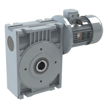
Our series S-SZ worm-gear speed reducer are made in nodular foundry G-25. Its square box allows the adaptation by anyone of its three mechanized faces.
The rigidity of this format comes given by the block, which supports itself the tension between the worm-gear and the wheel. For that reason its operating time ratio is higher than series MF.
If it is necessary, we are able to provide this kind of speed reducer in nodular foundry GGG-40, by this way it could be useful as a support of the machine.
Structural Features
The worm-gear reducer is made up of three main parts: housing, worm-gear and wheel.
The carcass are built out in nodular foundry GG-25 of GG-25 for each sizes of this model, which gives an exceptional behaviour to tiredness, vibrations, or in the event of any other impossible problem to avoid during the assembly.
The worm-gear is built out of cement steel and soaked, and the rectified flanks of teeth as well as the crown are built out of bronze DIN (GZ-CuSn 12 Ni2) and are melted on steel. Due to the mechanical work of these two parts having high quality, excellent performance and low noise levels have been achived.
El eje de salida es hueco, aunque permite la posibilidad de adaptarle un eje postizo.
The oil seal made of NITRILE BUTADIENE, according to DIN 3760, high quality bearings, an EPOXI-impregnated finish (2components), and grey-coloured SINGLE LAYER ENAMEL finish (2 components), RAL 7672, provide the most competitive ear reducer on the market.
Assembly Position
In order to set up a gear reducer and to make it work efficiently, the following instructions must be taken into account:
Backdriving
It is wise to pay attention to this factor when the gear reducer output shaft is driven instead of being a driver. Bearing in mind that one of the features of this worm-gear reducer is the fact that cannot be axle-driven by the output shaft (irreversibility), it is almost impossible to meet total irreversibility conditions, due to external factors such as vibrations, etcÖ This is why, when the application requires total irreversibility, it is advisable to make use of external brakes with enough power to avoid slipping.
It could be said that the conditions under which irreversibility can happen are as follows:
• output < 0,55 (see table of technical features).
Maintenance
This kind of gear reducer is provided with a permanent lubrication, so it does not need any kind of maintenance.
Lubrication
The lubrication of this gear reducer type is constant and comes as standard, with high quality refined oil which has antirust and antiwear products with Fe, Cu and alloy protectors that has CLP DIN 51517-3, FGZ level 12, AP GL-4, US 224, AGMA 250-04 level of quality; for that reason its maintenance is not needed.